русский
 中文简体
中文简体 Español
 Deutsch
 عربى
عربىContent
Quick Answer: What Is Insertion Loss?
Insertion loss is the reduction in signal strength that occurs as a signal passes through a cable, connector, or other component in a transmission path, measured in decibels (dB). In LAN cable terms, it describes how much weaker the signal is at the receiving end compared to the transmitting end, after traveling through the full length of cable plus every connector, splice, or patch panel along the way.
A lower insertion loss value means a cleaner, stronger signal reaches its destination. Cabling standards such as TIA-568 define maximum allowable insertion loss for each cable category — for example, a 100-meter Cat6 channel is generally specified to have insertion loss under 21.3 dB at 250 MHz. Cable runs or components that exceed the limit for their category will fail certification testing.
Understanding insertion loss matters at two very different points in a cable's life: during network installation, where installers verify finished cable performance, and during manufacturing, where it serves as a key quality indicator that reflects how consistently a production line is controlling material and process variables.
Why Insertion Loss Happens
Signal loss is not a defect by itself — some loss is expected and accounted for in every cabling standard. It comes from several physical sources that compound as a signal travels through a transmission path, and understanding each source helps explain why insertion loss limits differ across cable categories and lengths.
Main contributing factors
- Conductor resistance — copper itself resists current flow, and longer cable runs accumulate more resistive loss, which is why insertion loss is always specified as a function of cable length.
- Connectors and patch panels — every connection point introduces a small amount of additional loss, often around 0.1 to 0.3 dB per connector, which adds up quickly in installations with multiple patch points.
- Insulation material quality — dielectric properties of the insulation affect how much signal energy is absorbed as heat during transmission, with denser or inconsistent insulation generally producing higher loss.
- Frequency — insertion loss increases at higher signal frequencies, which is why high-speed categories like Cat6A specify stricter loss limits than Cat5e at the same length.
- Manufacturing defects — inconsistent conductor diameter, insulation voids, or poor twist control during production can all raise insertion loss above the expected baseline for a given cable length.
In practice, most of these factors are cumulative rather than isolated. A cable run that combines a slightly oversized conductor tolerance with several patch connections and a long physical distance can approach its category limit even when no single factor is, on its own, a clear defect.
Insertion Loss vs Other Cable Performance Metrics
Insertion loss is one of several parameters checked during cable certification, and it is often confused with related but distinct measurements. Understanding how these metrics differ is important for correctly diagnosing a failed cable test rather than assuming insertion loss is always the root cause.
| Parameter | What It Measures |
|---|---|
| Insertion loss | Total signal weakening from end to end of the transmission path |
| Return loss | Signal reflected back toward the source due to impedance mismatches |
| Near-end crosstalk (NEXT) | Interference coupled from adjacent twisted pairs near the signal source |
| Attenuation-to-crosstalk ratio (ACR) | The margin between signal strength and noise at the receiving end |
In practice, insertion loss and attenuation are often used interchangeably in cabling contexts, though insertion loss technically accounts for the entire link including connectors, while attenuation traditionally refers to loss in the cable medium alone.
A cable can pass an insertion loss test while still failing on return loss or crosstalk, which is why a complete certifier test checks all parameters together rather than treating insertion loss as a standalone pass/fail indicator.
How Insertion Loss Is Measured
Insertion loss is tested by comparing signal strength before and after it passes through the cable or component being evaluated.
- A known reference signal is injected at one end of the cable using a test source.
- A power meter or certified cable tester measures the signal strength that arrives at the other end.
- The difference between the input and output signal levels, expressed in dB, is the insertion loss value.
- The result is compared against the maximum allowable loss for the cable's category and length to determine pass or fail.
For fiber optic links, this same principle applies using an optical light source and power meter, while for copper LAN cable it is typically performed with a dedicated cable certifier that automatically applies the correct standard for the cable category being tested.
Most modern certifiers test insertion loss across a swept frequency range rather than at a single point, since loss generally increases with frequency. The result is usually presented as a graph showing measured loss against the standard's allowable limit line across the full frequency band relevant to the cable category, which makes it easy to spot whether a cable is marginal across the whole range or only fails near the top of its rated frequency.
How Manufacturing Quality Affects Insertion Loss
Because insertion loss is sensitive to conductor consistency and insulation quality, much of the work to minimize it happens during cable production rather than after installation. A cable that performs well on paper at the design stage can still fail certification in the field if production tolerances drift during manufacturing.
- Precise conductor diameter control during wire drawing keeps resistive loss consistent along the full cable length.
- Inline spark testing during insulation extrusion catches pinholes or voids that would otherwise increase signal absorption.
- Stable twist pitch during pair twisting helps control both crosstalk and insertion loss simultaneously, since uneven twisting affects impedance consistency.
- Consistent jacketing thickness and material purity reduce dielectric losses across the finished cable.
- Dry, properly stored polymer feedstock avoids moisture-related bubble formation in the insulation layer, which can otherwise create localized high-loss points along an otherwise compliant cable run.
Cable produced on a tightly controlled, fully monitored production line is significantly more likely to meet insertion loss specifications consistently across long manufacturing runs, compared to cable made on equipment without inline quality checks. This consistency matters most on large orders, where even a small percentage of out-of-spec cable can translate into a meaningful volume of rejected product at final certification.
Troubleshooting High Insertion Loss
When a cable run fails insertion loss testing, the cause is not always the cable itself. A systematic check helps narrow down the source before assuming a full cable replacement is needed.
- Confirm the cable run does not exceed the maximum length specified for its category, since length is the single largest contributor to total insertion loss.
- Inspect connectors and patch panel terminations for proper seating and correct termination technique, since poor crimps or punch-downs add disproportionate loss at each connection point.
- Check for excessive untwisting of pairs near terminations, which can raise both insertion loss and crosstalk at the same time.
- Review whether the cable category matches the application; using a lower category cable for a high-frequency application will produce insertion loss readings that exceed what the cable was ever designed to support.
- If failures are isolated to specific reels or production batches, treat this as a signal to review manufacturing process data for that batch rather than assuming a general design issue.
Controlling Insertion Loss on Our LAN Cable Production Lines
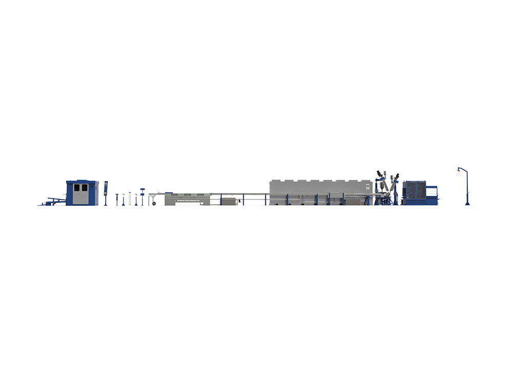
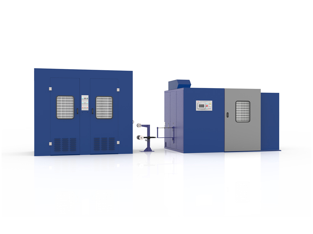
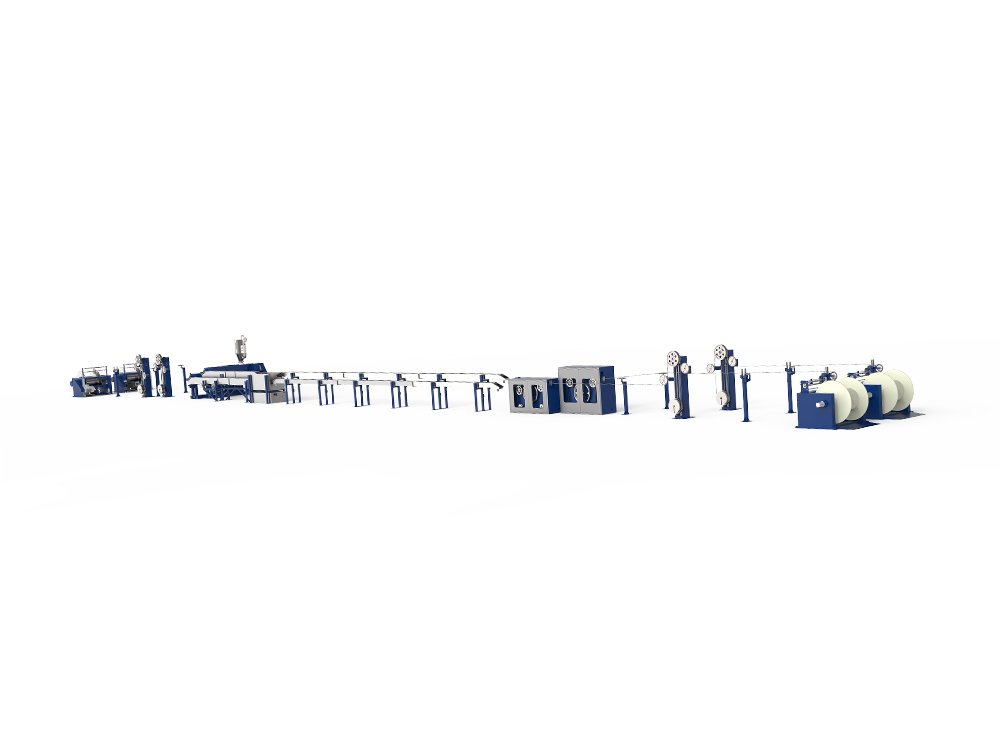
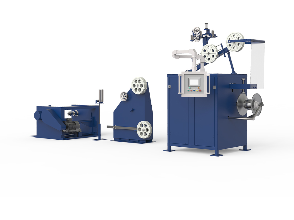
Zhangjiagang Dachen Machinery Manufacturing Co., Ltd. builds LAN cable production lines for Cat5e, Cat6, Cat6A, Cat7, and Cat8 cable with the goal of keeping insertion loss within category specification across every meter produced. Our equipment integrates precision wire drawing, inline insulation testing, and controlled pair twisting, with high-precision sensors feeding real-time data into the production control system to flag deviations before they affect the finished cable.
This level of in-process monitoring helps manufacturers reduce scrap and rework caused by insertion loss failures during final certification, supporting more predictable yield across large production volumes. For configuration details suited to a specific cable category or production speed, our engineering team can provide tailored technical guidance.