русский
 中文简体
中文简体 Español
 Deutsch
 عربى
عربىContent
- 1 LAN Cable Categories and Why They Drive Equipment Selection
- 2 Stage 1: Wire Drawing and Annealing
- 3 Stage 2: Insulation Extrusion — Standard vs. Physical Foam
- 4 Stage 3: Pair Twisting — The Core of LAN Cable Signal Performance
- 5 Stage 4: Cabling — Assembling Four Pairs Into a Cable Core
- 6 Stage 5: Shielding and Braiding
- 7 Stage 6: Outer Jacket Extrusion
- 8 Stage 7: Electrical Testing and Quality Certification
- 9 Stage 8: Fixed-Length Cutting, Coiling, and Packaging
- 10 Production Line Configuration Guide by Output Scale
- 11 What to Look for When Selecting a LAN Cable Production Line Supplier
- 12 Automation and Smart Manufacturing in LAN Cable Production
- 13 Frequently Asked Questions About LAN Cable Production Lines
- 13.1 What is the difference between a tandem line and a standard production line?
- 13.2 Can one production line manufacture multiple cable categories?
- 13.3 How much floor space is required for a complete LAN cable production line?
- 13.4 What international standards should LAN cable production line equipment meet?
- 14 Conclusion
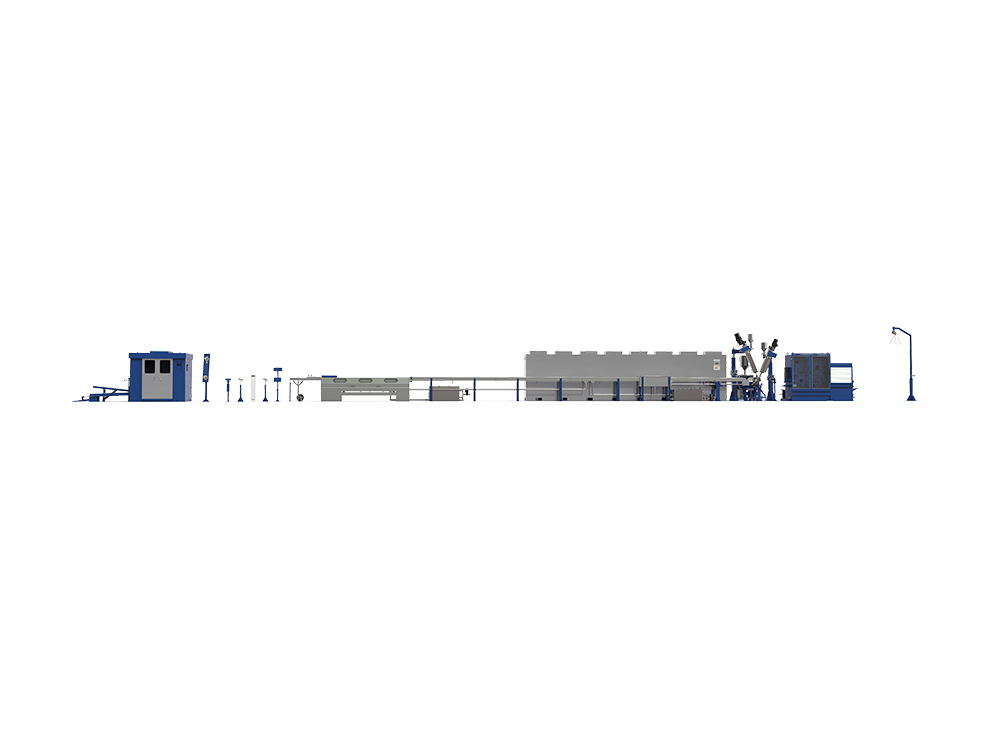
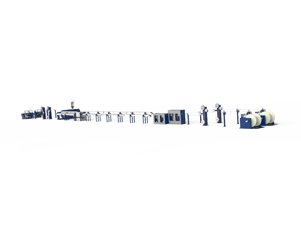
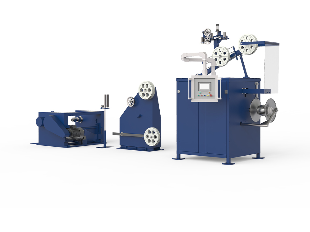
A LAN cable production line is a complete set of industrial equipment that transforms raw copper rod into finished, certified Ethernet cable — including Cat5e, Cat6, Cat6A, Cat7, and Cat8. It covers every core process: conductor drawing, insulation extrusion, pair twisting, cabling, sheathing, electrical testing, and fixed-length packaging. For network infrastructure manufacturers, cable distributors, and B2B equipment buyers, understanding how each stage of the production line operates is the foundation for making sound decisions on equipment investment, output quality control, and long-term production efficiency.
Global demand for structured cabling continues to grow in step with data center expansion, smart building development, and the ongoing rollout of high-speed enterprise networks. As transmission requirements advance from 1 Gbps to 10 Gbps and beyond, the manufacturing equipment used to produce those cables must evolve in parallel. This article examines the full workflow of a LAN cable production line — from the first wire draw to the last packaged spool — and outlines the key technical and commercial considerations that buyers must evaluate when selecting equipment.
LAN Cable Categories and Why They Drive Equipment Selection
LAN cables are standardized by international bodies including ANSI/TIA (North America) and ISO/IEC (global). The most commercially significant categories currently in production are Cat5e, Cat6, Cat6A, Cat7, and Cat8, each with different conductor gauges, insulation types, shielding requirements, and performance targets. Understanding these distinctions is essential because the cable category being produced directly determines the configuration and complexity of the production line required.
LAN cables are also divided by shielding type. UTP (Unshielded Twisted Pair) cables — predominant in North America and standard Cat5e/Cat6 installations globally — require no foil or braid shielding, which simplifies the production line. STP, FTP, and S/FTP (Shielded Twisted Pair) variants, favored in European markets and high-interference industrial environments, require additional shielding stages and more sophisticated jacketing processes. The target market geography therefore directly influences equipment configuration.
| Cable Category | Standard | Conductor Gauge | Insulation Type | Typical Shielding | Max Bandwidth | Max Data Rate |
|---|---|---|---|---|---|---|
| Cat5e | TIA-568-C.2 | 24 AWG | Solid HDPE | UTP | 100 MHz | 1 Gbps |
| Cat6 | TIA-568-C.2 | 23 AWG | Foam HDPE | UTP / STP | 250 MHz | 10 Gbps (≤55 m) |
| Cat6A | TIA-568-C.2 | 23 AWG | Physical Foam PE | S/FTP | 500 MHz | 10 Gbps (≤100 m) |
| Cat7 | ISO/IEC 11801 | 23 AWG | Physical Foam PE | S/FTP | 600 MHz | 10 Gbps (≤100 m) |
| Cat8 | TIA-568-C.2-10 | 22 AWG | Skin-Foam-Skin PE | S/FTP | 2000 MHz | 25–40 Gbps |
A manufacturer targeting Cat5e and standard Cat6 requires a fundamentally different equipment set than one producing Cat6A, Cat7, or Cat8. Higher-category cables demand physical foam insulation lines, precision pair twisting machinery with tighter pitch tolerances, more complex shielding modules, and more comprehensive electrical testing systems. Buyers planning for multi-category production should work with equipment suppliers to design a modular line that can be incrementally upgraded as product requirements expand.
Stage 1: Wire Drawing and Annealing
Every LAN cable production line begins with wire drawing. Raw copper rod — typically 8 mm in diameter — is pulled through a progressive series of tungsten carbide dies, each reducing the cross-sectional area incrementally. Because the wire's volume is conserved during this process, the diameter decreases as length increases. Lubricant is continuously flooded over the dies during drawing to reduce friction, cool the contact zone, and extend die service life.
The first wire draw produces a coiled conductor at a heavier gauge — commonly 10, 12, or 14 AWG. This intermediate stock is then transferred to a secondary drawing station where the conductor is reduced to its final target gauge: 24 AWG for Cat5e, 23 AWG for Cat6 and Cat6A, and 22 AWG for Cat8. Each progressive drawing pass work-hardens the copper through a process known as cold-working, which increases tensile strength but also introduces brittleness and reduces ductility.
To restore the copper's flexibility and workability, the drawn conductor undergoes annealing immediately after the final draw. The wire is rapidly heated to approximately 450°F (232°C) in a controlled nitrogen atmosphere — the inert gas prevents surface oxidation at elevated temperatures. This thermal treatment relieves the internal stresses introduced by cold-working, restoring the conductor's ductility and ensuring it can withstand the mechanical handling of subsequent production stages without cracking or breaking.
Modern high-performance drawing machines incorporate tandem line configurations, where the drawing and annealing stages are physically integrated into a single continuous process. Rather than coiling the drawn wire and transporting it to a separate annealing furnace, the wire passes directly from the drawing dies through an inline annealing section, eliminating the intermediate handling step. This integration directly increases line speed, reduces labor input, and improves conductor surface quality by minimizing oxide formation between stages.
A key quality parameter at this stage is conductor concentricity and surface smoothness. Any ovality or surface defect in the drawn wire will propagate through the insulation extrusion and twisting stages, ultimately affecting the cable's electrical performance. Premium drawing machines use real-time diameter monitoring with laser gauges to verify output consistency against target tolerances throughout the entire run.
Stage 2: Insulation Extrusion — Standard vs. Physical Foam
After drawing and annealing, each individual conductor receives a thermoplastic insulation layer through an extrusion process. The insulation serves two primary functions: it provides electrical isolation between conductors within the cable, and its dielectric properties directly influence the cable's signal propagation characteristics — particularly attenuation, capacitance, and impedance. The choice of insulation material and extrusion method is one of the most technically significant decisions in configuring a LAN cable production line.
Solid HDPE Insulation
For Cat5e production, solid High-Density Polyethylene (HDPE) insulation is the standard choice. Solid HDPE is cost-effective, mechanically robust, and straightforward to extrude at high line speeds. It provides sufficient dielectric performance for 100 MHz transmission requirements. Cat5e solid insulation lines are therefore well-suited to manufacturers prioritizing high-volume output at lower capital cost.
Chemical Foam Insulation
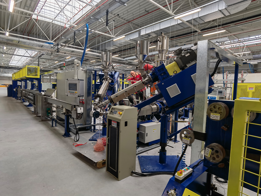
For Cat6 and entry-level Cat6A, many manufacturers use chemical foaming, in which a foaming masterbatch (commonly Azodicarbonamide-based) is blended with HDPE in a ratio of approximately 1–3%. At the extrusion temperature, the foaming agent decomposes and generates gas bubbles within the insulation, creating a foam structure with a typical expansion rate of 15–25%. The foam structure lowers the dielectric constant of the insulation compared to solid HDPE, which reduces signal attenuation and capacitance — both critical parameters for Cat6 performance. Chemical foam lines are significantly less expensive to purchase and operate than physical foam systems, making them a practical choice for manufacturers entering the Cat6 market.
Physical Foam Insulation
For Cat6A, Cat7, and Cat8, physical foaming (also called gas injection foaming) is the required method. In physical foam extrusion, nitrogen or carbon dioxide gas is injected directly into the molten HDPE inside the extruder screw, creating a uniform cellular foam structure. Physical foaming achieves expansion rates of 50% or higher, producing a significantly lower dielectric constant than chemical foaming. This is essential for the high-frequency signal integrity requirements of 500 MHz (Cat6A), 600 MHz (Cat7), and 2000 MHz (Cat8) cables.
Cat8 cables specifically require a skin-foam-skin (SFS) insulation structure: a solid skin layer, a physical foam core, and an outer solid skin layer. The solid skin layers provide mechanical protection and dimensional stability, while the foam core delivers the ultra-low dielectric constant needed for 2000 MHz transmission. SFS extrusion requires a co-extrusion crosshead with three independent material channels and precise pressure control, making it technically the most demanding insulation process in the LAN cable product range.
Modern physical foam insulation lines integrate online quality monitoring systems that track conductor diameter, insulation outer diameter, concentricity, and capacitance in real time. These systems can detect deviations from target parameters within seconds and trigger automatic line speed adjustment or alarm functions — reducing scrap and ensuring consistent output quality across long production runs.
| Insulation Method | Applicable Category | Foam Expansion Rate | Dielectric Constant | Equipment Complexity |
|---|---|---|---|---|
| Solid HDPE | Cat5e | 0% | ~2.3 | Low |
| Chemical Foam HDPE | Cat6 | 15–25% | ~2.0–2.1 | Medium |
| Physical Foam PE | Cat6A / Cat7 | 40–55% | ~1.6–1.8 | High |
| Skin-Foam-Skin (SFS) | Cat8 | 50%+ | ≤1.5 | Very High |
Stage 3: Pair Twisting — The Core of LAN Cable Signal Performance
Pair twisting is technically the most critical process in LAN cable manufacturing. Two insulated conductors are twisted together to form a twisted pair, a configuration that provides the cable's fundamental electromagnetic noise immunity. The twisting principle works by causing the electromagnetic fields generated by current flow in each conductor to partially cancel each other out — a phenomenon known as common-mode rejection. The tighter and more consistent the twist, the greater the noise cancellation and the lower the crosstalk between adjacent pairs.
The twist pitch (also called lay length) — the axial distance over which the pair completes one full 360° rotation — is a precisely controlled parameter. Different pairs within the same cable are intentionally assigned different twist pitches to minimize near-end crosstalk (NEXT) and far-end crosstalk (FEXT) between pairs. The consistency of the twist pitch along the entire cable length directly determines whether the finished cable will pass TIA or ISO/IEC electrical performance certification testing.
Pair Twisting Machine Types
Three main categories of pair twisting machine are used in LAN cable production:
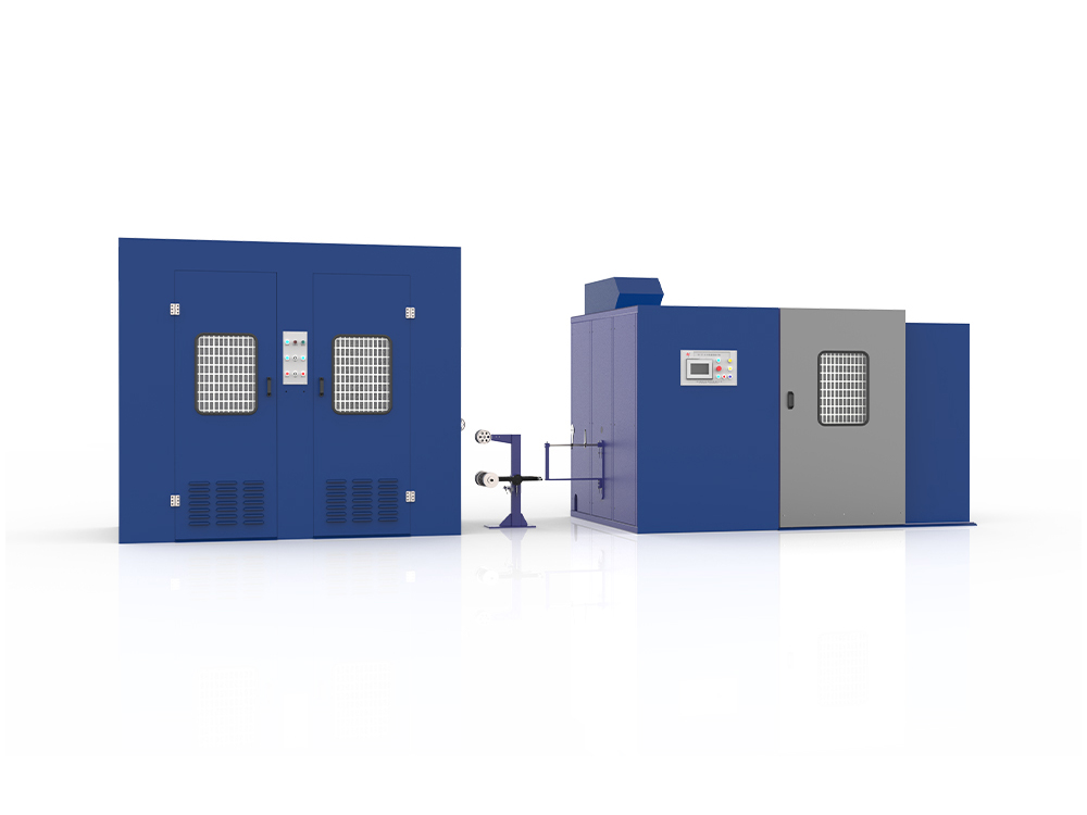
- Double Twist Machines: The standard workhorse for Cat5e through Cat6A. Two twists are produced per bow rotation, improving production efficiency compared to single-twist designs. Double twist machines suitable for LAN cable production typically operate at speeds up to 2,400 twists per minute, with pitch accuracy within ±2%.
- Triple Twist Machines: Produce three twists per bow rotation, achieving approximately 1.5× the output speed of a standard double twist machine at equivalent back-twist rates. Triple twist machines are well-suited to high-volume Cat6 and Cat7 production where throughput speed is a key operational priority.
- Quadruple Twist Machines: Deliver approximately 2× the speed of a conventional double twist machine. Ideal for very high-volume Cat5e and Cat6 production environments where continuous output and minimal machine changeover time are the primary considerations.
A critical feature of all professional-grade pair twisting machines is the back-twist mechanism. As the pair is twisted, torsional stress accumulates in the insulated wire. Without a back-twist system, this stress would cause the finished twisted pair to spring back and unwind when tension is released, producing inconsistent pitch. The back-twist payoff unwinds the wire at a controlled rate during the twisting process, neutralizing torsional stress and ensuring the twist pitch remains stable throughout the reel.
For Cat6A, Cat7, and Cat8 production, the pair twisting machine must also maintain constant and stable pay-off tension. Variations in pay-off tension directly affect the twist pitch consistency and the dimensional stability of the pair, both of which feed into the impedance uniformity of the finished cable. High-precision twisting machines use servo-motor-driven pay-off systems with closed-loop tension control to ensure that tension variation remains within acceptable limits throughout the entire bobbin — from full load to near-empty.
Modern pair twisting machines are equipped with PLC control systems and color touchscreen HMIs, allowing operators to program and store twist recipes for each cable category. Parameters including target lay length, line speed, back-twist ratio, and tension setpoints are stored digitally, enabling fast and accurate changeovers when switching between cable types.
Stage 4: Cabling — Assembling Four Pairs Into a Cable Core
After four twisted pairs have been produced, they are assembled together into a cable core by a cabling machine (also called a stranding machine or laying machine). The four pairs are fed from pay-off reels and twisted together as a unit around the cable axis. Each pair is assigned a different overall twist pitch to maintain the inter-pair crosstalk isolation already established by the pair twisting stage.
For Cat6 and higher categories, a cross-member spline separator is inserted at the center of the cable core during cabling. The spline — typically a cruciform plastic element — physically separates the four pairs from each other and from the center of the cable, maintaining consistent pair geometry and preventing pairs from migrating against each other under the mechanical forces of installation and use. The spline is a key contributor to the crosstalk performance advantage of Cat6 over Cat5e and is a mandatory inclusion in Cat6 production lines.
Single Twist vs. Double Twist Cabling Machines
Cabling machines are available in both single-twist and double-twist configurations. Single twist cabling machines are commonly used for Cat6, Cat7, and Cat8 production where the four twisted pairs need to be assembled with tape wrapping applied to individual pairs during the twisting process. The machine performs the overall twisting of the four pairs while simultaneously applying longitudinal tape or foil to each pair as required by the shielding specification.
Double twist cabling machines are higher-capacity units designed specifically for the most demanding LAN cable applications. These machines handle the assembly of complex cable cores for Cat6A, Cat7, and Cat8, where multiple shielding layers and precise pair geometry must be maintained simultaneously. Double twist cabling machines are built with high-rigidity frame structures to minimize vibration at elevated operating speeds, and they incorporate comprehensive control and monitoring systems to manage the increased number of process variables involved in high-category cable production.
For shielded cable variants, individual pair taping or foiling is applied as an integrated step within the cabling process. A longitudinal taping head feeds aluminum-laminated foil tape around each pair as it passes through the cabling head, creating per-pair shielding before the overall cable shield is applied in the subsequent stage. The overlap percentage and tension of the tape application are closely controlled parameters that affect both the shielding effectiveness and the overall cable diameter.
Stage 5: Shielding and Braiding
For STP, FTP, and S/FTP cable variants, a dedicated shielding stage follows cabling. This stage applies an overall electromagnetic shield around the assembled cable core, providing protection against external electromagnetic interference (EMI) and containing the cable's own radiated emissions. The specific shielding configuration varies by cable category and market specification.
Foil Shielding
Aluminum-laminated polyester (Al/PET) foil tape is longitudinally applied over the cable core to create an overall foil shield. The foil provides effective shielding against high-frequency interference and adds minimal diameter to the cable. A drain wire — a bare tinned copper conductor — is typically included in contact with the foil to provide a low-resistance ground path for the shield. Foil shielding is standard for FTP (Foiled Twisted Pair) cables and for the overall shield layer of S/FTP designs.
Braided Shielding
For applications requiring superior low-frequency shielding and mechanical durability, a braided shield of tinned copper or bare copper wire is applied using a cable mesh winding machine (braiding machine). The braiding machine feeds multiple fine copper wires from spindles arranged in a circular carrier, interlacing them in a helical pattern over the cable core. The coverage percentage of the braid — typically specified at 85–95% — directly determines the shielding effectiveness at lower frequencies. Braided shielding is commonly specified for industrial cable applications and for the overall shield of S/FTP Cat7 and Cat8 cables.
Cable braiding machines designed for LAN cable production typically support cable diameters up to 14 mm and can operate at production speeds up to 600 meters per hour. The number of spindles determines the maximum achievable braid coverage: machines with higher spindle counts can achieve higher coverage percentages at the same line speed. Key machine parameters — including carrier rotation speed, braid angle, and coverage percentage — are managed through PLC control systems.
Stage 6: Outer Jacket Extrusion
The cable core — whether shielded or unshielded — then passes through the jacket extrusion line, where a protective outer sheath is applied. The jacket extrusion stage is mechanically similar to the insulation extrusion stage but operates at a larger scale, covering the entire multi-pair core rather than individual conductors.
Jacket Material Selection
The choice of jacket material is determined by the installation environment and applicable fire safety standards:
- PVC (Polyvinyl Chloride): The most widely used jacket material for general commercial and residential installations. PVC provides good mechanical protection, flexibility, and cost-effectiveness. Standard PVC jackets comply with CM (Communications) and CMR (Communications Multipurpose Riser) fire ratings under UL standards.
- LSZH (Low Smoke Zero Halogen): Required in enclosed public spaces, transportation infrastructure, and European building installations. LSZH compounds release minimal toxic smoke and no halogen gases when exposed to flame, significantly improving occupant safety in fire scenarios. LSZH jacket lines require higher extrusion temperatures and more precise control compared to standard PVC lines.
- PE (Polyethylene): Used for outdoor-rated cables. PE provides excellent moisture resistance and UV stability, making it appropriate for direct burial and outdoor aerial installations.
- PLENUM-rated compounds: Required for cables routed through air-handling spaces (plenum areas) in commercial buildings. Plenum jackets produce minimal smoke and no corrosive gases at elevated temperatures.
A rip cord is embedded within the jacket of most LAN cables during the extrusion process. The rip cord — a high-tensile polyester fiber thread — allows field installers to split the jacket longitudinally without a cutting tool, simplifying termination in tight spaces. For STP variants, the rip cord must be positioned between the foil shield and the outer jacket.
After extrusion, the jacketed cable passes through a water trough for rapid cooling before reaching the capstan. The cooling trough length and water temperature are calibrated to achieve complete jacket crystallization at the target line speed. Insufficient cooling results in jacket surface defects and dimensional instability; excessive cooling can cause jacket stress cracking. A high-frequency spark tester is positioned downstream of the cooling trough to perform continuous inline insulation integrity testing — any pinhole or void in the jacket will cause a spark discharge and trigger an alarm.
Stage 7: Electrical Testing and Quality Certification
No finished LAN cable leaves a production line without passing a comprehensive set of electrical performance tests. These tests verify that the cable meets the relevant TIA or ISO/IEC category specifications and that no manufacturing defects have compromised performance. The testing stage is not a formality — it is the verification step that validates the entire upstream manufacturing process.
Key Electrical Parameters Tested
- DC Resistance and Resistance Unbalance: Verifies conductor continuity and uniformity. High resistance indicates conductor damage or an undersized conductor; high resistance unbalance indicates unequal conductor cross-sections within a pair, which degrades common-mode rejection.
- Mutual Capacitance: A key parameter influenced by insulation thickness, foam expansion rate, and conductor concentricity. Capacitance that exceeds the specified limit will cause the cable to fail attenuation testing at higher frequencies.
- Near-End Crosstalk (NEXT) and Far-End Crosstalk (FEXT): Measures the electromagnetic coupling between adjacent pairs at both ends of the cable. This parameter is most sensitive to pair geometry consistency and twist pitch uniformity, making it the primary quality indicator for the pair twisting and cabling stages.
- Return Loss: Quantifies impedance discontinuities along the cable length. High return loss indicates geometric inconsistency in the cable — typically caused by twist pitch variation, uneven insulation wall thickness, or mechanical damage during processing.
- Attenuation (Insertion Loss): Measures signal power loss per unit length as a function of frequency. Attenuation is determined by conductor resistance, insulation dielectric constant, and jacket material properties. It is the fundamental performance parameter for long-distance signal transmission.
- Impedance: LAN cables are standardized at 100 Ω characteristic impedance. Impedance uniformity along the cable length — the consistency of the impedance value at every point — is critical for minimizing reflections in high-speed networks.
For Cat6A and higher, testing must cover frequencies up to 500 MHz; for Cat8, testing extends to 2000 MHz. Cables failing any test parameter are either rejected or downgraded to a lower category. Statistical Process Control (SPC) systems integrated into modern production lines track test results across batches and identify trends in key parameters before they lead to outright failures, enabling proactive process adjustments that reduce scrap rates and improve overall yield.
Stage 8: Fixed-Length Cutting, Coiling, and Packaging
The final stage of the LAN cable production line is fixed-length cutting, coiling, and packaging. Tested cable is wound onto spools or into coils at precisely measured lengths, then labeled and packed for shipment. This stage must be executed with the same precision as earlier manufacturing stages — inaccurate length measurement leads to customer disputes, and poor coiling quality causes cable kinking and installation problems in the field.
The most common commercial packaging format for bulk LAN cable supply is the 305-meter (1,000-foot) pull box. Cable is wound into a cardboard box with a center pull configuration, allowing the cable to be pulled from the center of the coil during installation without the box rotating. This format is standard for Cat5e and Cat6 distribution to installers and system integrators globally.
For patch cord and cut-to-length supply, automated integrated coiling and spooling machines perform the cutting and winding in a single operation. These machines use encoder-based length measurement systems to ensure cutting accuracy within tight tolerances, and they apply shrink wrap or banding to the finished coil before it proceeds to the labeling station. High-output coiling machines can process multiple cable reels simultaneously, enabling continuous operation without manual intervention.
Production Line Configuration Guide by Output Scale
There is no universal LAN cable production line configuration. The optimal equipment selection depends on the production scale, target cable categories, and capital budget of the buyer. The following framework provides a practical starting point for matching equipment configuration to production requirements.
| Production Scale | Target Output | Recommended Cable Categories | Key Equipment | Notes |
|---|---|---|---|---|
| Entry-Level | Low–Medium | Cat5e / Cat6 | Single extruder + double twist machine + cantilever cabling machine + sheathing line + coiler | Chemical foam or solid insulation; suitable for developing markets |
| Mid-Scale | Medium–High | Cat6 / Cat6A | Tandem drawing-insulation line + triple/quad twist machine + single twist cabling machine + shielding stage + sheathing line | Physical foam insulation required for Cat6A; SPC integration recommended |
| Full-Scale | High / Industrial | Cat6A / Cat7 / Cat8 | SFS physical foam line + double twist cabling machine + braiding machine + LSZH sheathing + full electrical test system + automated packaging | Full process automation; designed for data center and industrial cable supply |
A production line capable of stable output at 1,200 meters per minute with full-process automated control — covering conductor drawing through fixed-length packaging — represents the current standard for high-capacity LAN cable manufacturing. Facilities operating at this level can achieve annual output volumes that support large-order commitments to system integrators and cable distributors globally, with the consistency and certification documentation required for commercial infrastructure projects.
What to Look for When Selecting a LAN Cable Production Line Supplier
For buyers evaluating LAN cable production line suppliers, the following criteria are the most meaningful indicators of long-term reliability and value. Equipment cost is one factor, but the total cost of ownership — including commissioning time, maintenance burden, spare parts availability, and technical support responsiveness — typically determines the real return on investment.
In-House Engineering Capability
A supplier with control over both the mechanical structure and the electrical control system of its production lines can resolve technical issues faster, deliver customized configurations more reliably, and provide more accurate process guidance during commissioning. Suppliers who source critical components from third parties and integrate them without in-depth understanding of the system are more limited in their ability to support customers when problems arise. Evaluating a supplier's engineering team — its size, seniority, and the proportion dedicated to R&D — provides meaningful insight into the technical depth available to support your operation.
Modular Design and Upgrade Path
LAN cable market requirements evolve over time. A production line that supports Cat6 today may need to be upgraded to Cat6A or Cat7 within the next several years as market demand shifts upward. Equipment that has been designed with modularity in mind — allowing the insulation extrusion module, the shielding stage, or the testing system to be upgraded or added independently — provides significantly better long-term value than monolithic configurations that must be replaced in their entirety to support new cable categories.
Quality Certifications and Process Documentation
ISO 9001 certification demonstrates that a supplier operates a documented quality management system covering design, production, testing, and after-sales processes. CE marking on individual machines verifies compliance with relevant EU safety directives — a requirement for buyers supplying European markets. Beyond certifications, professional suppliers provide comprehensive delivery documentation for each production line, including electrical circuit diagrams, mechanical layout drawings, operation manuals, and maintenance schedules. This documentation package is essential for the buyer's own maintenance team and for regulatory compliance in markets that require facility audit documentation.
After-Sales Support and Spare Parts Availability
Production line downtime has a direct and calculable cost. A supplier's commitment to after-sales support — specifically the speed of technical response and the availability of critical spare parts — is therefore a key procurement criterion. Suppliers offering 24-hour engineer response services and 12-month warranty coverage on spare parts provide a measurable safety net for buyers entering production with new equipment. Buyers should also evaluate whether the supplier can arrange on-site installation and commissioning support, and whether remote troubleshooting assistance is available for issues that arise after the commissioning period ends.
International Export Experience
A supplier with established export history to multiple international markets has necessarily addressed the logistical, technical, and regulatory requirements of cross-border equipment delivery. This includes experience with different power specifications (voltage, frequency, phase), compliance with destination-country import regulations, and the ability to prepare documentation in formats accepted by international buyers. Suppliers whose equipment is operating in verified installations across multiple countries and regions provide more reliable reference points for performance validation than those with only domestic track records.
Zhangjiagang Dachen Machinery Manufacturing Co., Ltd., headquartered in Jinfeng Town, Zhangjiagang — a nationally recognized production base for wire and cable equipment in Jiangsu Province — offers complete LAN cable production line solutions covering all stages from conductor drawing through finished cable packaging. With a team of over 60 professionals (including senior engineers accounting for more than 20% of staff), ISO 9001:2008 certification, and equipment exported to more than 20 countries across South America, Europe, and Asia, Dachen provides the technical breadth and international experience that B2B buyers require. The company's in-house control over both mechanical and electrical system development ensures fast delivery, flexible customization, and dependable technical support throughout the equipment lifecycle.
Automation and Smart Manufacturing in LAN Cable Production
The integration of automation and digital control technology into LAN cable production lines has fundamentally changed the economics and quality standards achievable in the industry. What was once a labor-intensive manufacturing process dependent on skilled operators at multiple stages is increasingly managed by interconnected PLC systems, real-time data acquisition platforms, and automated response mechanisms that reduce human error and maintain consistent output quality across extended production runs.
Automated Wire Feeding and Tension Control
Automated wire feeding systems precisely measure and cut conductors to specified lengths before feeding them into the extrusion and twisting stages. By eliminating manual measurement and handling, these systems remove a significant source of length variation and reduce material waste caused by operator error. Servo-driven pay-off systems with closed-loop tension feedback maintain constant wire tension regardless of reel diameter, ensuring consistent insulation concentricity and twist geometry from the beginning to the end of each reel.
Real-Time Process Monitoring and SPC
Advanced production lines integrate Statistical Process Control (SPC) systems that collect measurement data from inline sensors across all production stages. Conductor diameter, insulation outer diameter, capacitance, and spark test results are logged continuously and analyzed against control limits. When a parameter approaches — but has not yet reached — its specification limit, the SPC system alerts operators or triggers automatic corrective adjustments, preventing defects before they occur rather than detecting them after the fact. SPC data also provides a complete production history for each cable reel, supporting traceability requirements for quality-sensitive markets.
Digital Recipe Management
Modern PLC-controlled production lines store digital production recipes for each cable category and product specification. When switching from Cat6 to Cat6A production, for example, operators select the relevant recipe from the HMI and the system automatically sets target speeds, temperatures, tension values, twist pitches, and test limits across all linked machine stations. This eliminates the manual parameter entry and verification steps that previously made product changeovers time-consuming and error-prone. One-button acceleration and deceleration functions allow smooth line speed ramp-up and ramp-down without requiring manual adjustments at multiple stations simultaneously.
Frequently Asked Questions About LAN Cable Production Lines
What is the difference between a tandem line and a standard production line?
A tandem line integrates wire drawing, annealing, preheating, and insulation extrusion into a single continuous process on one machine platform. A standard line separates these stages, requiring the wire to be coiled, stored, and transferred between stations. Tandem lines offer higher line speeds, reduced floor space requirements, lower labor costs, and better conductor surface quality — all at a higher initial capital cost. For medium to high-volume production, the tandem configuration typically delivers a faster return on the investment premium.
Can one production line manufacture multiple cable categories?
Yes, with appropriate equipment selection. A modular LAN cable production line can be configured to produce Cat5e, Cat6, and Cat6A by switching insulation parameters, twisting recipes, and applying the shielding stage selectively. However, Cat8 production with SFS insulation typically requires a dedicated physical foam co-extrusion line. Buyers planning for multi-category flexibility should confirm modular compatibility with their equipment supplier at the specification stage.
How much floor space is required for a complete LAN cable production line?
Floor space requirements vary significantly by line configuration and production scale. A complete production line — including drawing, insulation, twisting, cabling, sheathing, testing, and packaging — typically requires a dedicated production hall. Equipment suppliers should provide a detailed floor plan layout, showing the footprint, access requirements, and utility connections (power, water, gas) for each machine station. This information is essential for facility planning well before equipment delivery.
What international standards should LAN cable production line equipment meet?
Equipment should comply with relevant safety standards for the destination market — CE marking for Europe, UL or CSA certification for North America. The cable produced on the line should be verifiable against TIA-568 (North America), ISO/IEC 11801 (international), and IEC 61156 (component standards). Buyers supplying multiple markets should ensure their testing system supports verification against all applicable regional standards, as test limits vary between TIA and ISO/IEC specifications for the same cable category.
Conclusion
A complete LAN cable production line is a precision manufacturing system in which every stage — from wire drawing and annealing, through insulation extrusion, pair twisting, cabling, shielding, jacket application, electrical testing, and final packaging — contributes directly to the quality and performance certification of the finished cable. No stage can be treated in isolation: the output quality of each step is both a function of its own process parameters and the input quality received from the stage before it.
For B2B buyers evaluating equipment investment, the decision should be grounded in a clear understanding of the target cable categories, the production scale required, and the degree of automation appropriate for the operational context. Entry-level lines for Cat5e and Cat6 can be configured cost-effectively with solid or chemical foam insulation and standard double twist machinery. High-performance Cat6A, Cat7, and Cat8 production demands physical foam extrusion, high-precision double twist cabling machines, comprehensive shielding stages, and integrated SPC-based quality systems.
Selecting the right equipment supplier means evaluating not only machine specifications but also engineering depth, quality certifications, after-sales support infrastructure, and international delivery experience. A supplier who can provide complete turnkey support — from initial equipment configuration through commissioning, operator training, and ongoing technical assistance — is a long-term production partner, not simply a one-time vendor. For manufacturers building or expanding a LAN cable production operation, that partnership represents one of the most consequential choices in the facility's development.