русский
 中文简体
中文简体 Español
 Deutsch
 عربى
عربىContent
- 1 Stage 1 — Wire Drawing: Reducing Conductor Diameter to Specification
- 2 Stage 2 — Stranding: Bundling Conductors for Flexibility and Current Capacity
- 3 Stage 3 — Insulation Extrusion: Applying the Dielectric Layer
- 4 Stage 4 — Cabling and Core Assembly: Building Multi-Conductor Cables
- 5 Stage 5 — Shielding and Armoring: Protecting Against Interference and Mechanical Damage
- 6 Stage 6 — Outer Sheath Extrusion: The Final Protective Jacket
- 7 Stage 7 — Electrical and Mechanical Testing: Verifying Performance Before Shipment
- 8 Key Quality Control Points Across the Entire Cable Production Line
- 9 How Cable Production Line Technology Affects Product Quality and Buyer Decisions
- 10 From Raw Rod to Finished Drum: A Summary of the Complete Process
The manufacturing process of cables is a multi-stage industrial workflow that transforms raw copper or aluminum conductors into finished, insulated wire products ready for electrical, data, or mechanical applications. From wire drawing and stranding to insulation extrusion and final testing, each stage on an industrial cable production line is tightly controlled to meet international safety and performance standards. Understanding this process helps procurement engineers, project managers, and sourcing teams make more informed decisions when selecting cable suppliers or evaluating product quality.
Whether you are sourcing power cables, control cables, or communication cables for large-scale infrastructure projects, the quality of the final product depends entirely on the precision and consistency of each step in the production chain. This article walks through the complete manufacturing sequence, explains the equipment involved, and highlights the quality control measures that separate reliable cables from substandard ones.
Stage 1 — Wire Drawing: Reducing Conductor Diameter to Specification
The first step in any industrial cable production line is wire drawing. Raw copper or aluminum rod — typically supplied in coils with a diameter of around 8 mm — is pulled through a series of progressively smaller tungsten carbide dies. Each pass reduces the cross-sectional area of the conductor while simultaneously increasing its length and tensile strength. Depending on the target gauge, a single rod may pass through 20 or more drawing stages.
Wire drawing machines operate at high speed, with cooling lubricants applied continuously to reduce friction and heat buildup. Die wear monitoring is a critical maintenance task at this stage — even minor die deformation leads to dimensional inconsistency that compounds in later processes. After drawing, the fine wire is wound onto bobbins or spools for the next stage. For applications requiring soft, flexible conductors, an annealing process (controlled heating and slow cooling) is applied immediately after drawing to restore ductility.
Conductor diameters commonly produced at this stage range from 0.1 mm for fine instrument wire to over 3 mm for heavy-duty power conductors, with tolerances held to within ±0.01 mm on precision lines.
Stage 2 — Stranding: Bundling Conductors for Flexibility and Current Capacity
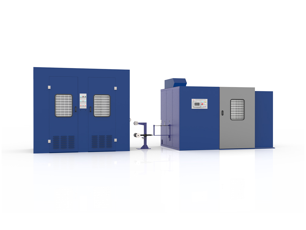
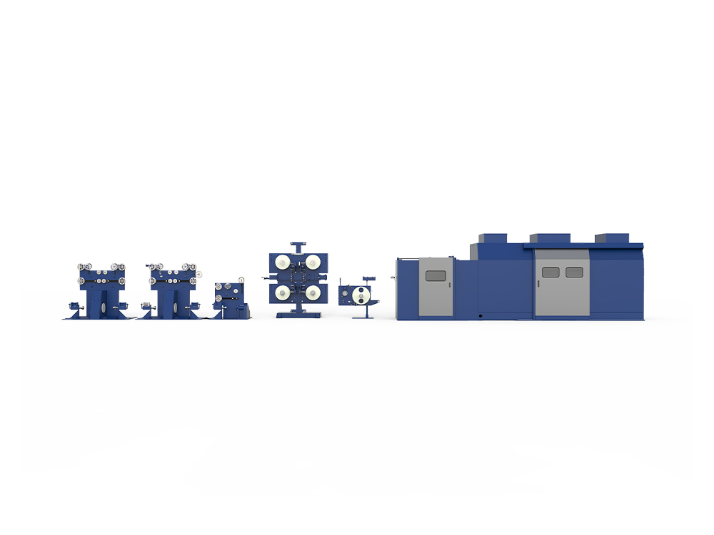
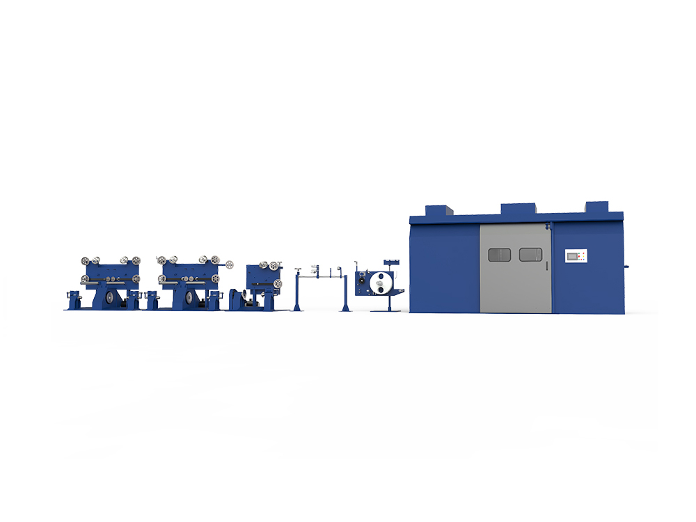
A single solid wire is only suitable for fixed installations. For cables that require flexibility — such as those used in motor connections, mobile machinery, or building wiring — multiple fine wires are twisted together in a process called stranding. The stranding machine takes a defined number of individual wires from bobbins and helically twists them around a central core wire at a controlled lay length (the distance required for one complete twist).
The configuration of a stranded conductor directly affects its flexibility class. Under IEC 60228, conductors are categorized from Class 1 (solid) to Class 6 (extra-flexible), with Class 5 and Class 6 requiring very fine individual wires twisted in multiple concentric layers. Buncher machines are used for finer, more flexible constructions, while rigid stranding machines are used for heavier, concentrically stranded conductors found in medium-voltage power cables.
Lay length selection is not arbitrary — shorter lay lengths increase flexibility but also increase the total length of wire used per meter of cable, which has a direct impact on material cost and electrical resistance. Production engineers must balance these trade-offs based on end-use specifications.
Stage 3 — Insulation Extrusion: Applying the Dielectric Layer
Insulation extrusion is the defining step that transforms a bare conductor into a functional cable core. The stranded conductor is fed continuously through a cross-head extruder, where molten thermoplastic or thermoset compound is applied uniformly around the conductor under pressure. The most common insulation materials used across the cable industry include:
- PVC (Polyvinyl Chloride) — widely used for low-voltage building wiring; cost-effective and flame-retardant
- XLPE (Cross-Linked Polyethylene) — preferred for medium- and high-voltage cables; offers superior thermal performance and higher current-carrying capacity
- LSZH (Low Smoke Zero Halogen) — mandatory in confined or public spaces such as tunnels, subways, and data centers
- EPR (Ethylene Propylene Rubber) — used in flexible, high-temperature, or shipboard applications
- Silicone — used for extreme-temperature environments and medical-grade applications
The extruder screw speed, melt temperature, and line speed must be precisely synchronized to maintain uniform wall thickness. Even small variations — such as a 0.05 mm eccentricity in the insulation wall — can cause voltage stress concentration that leads to premature dielectric failure in service. Inline diameter gauges and spark testers are standard equipment immediately downstream of the extruder on a well-configured industrial cable production line.
For XLPE cables, a separate cross-linking step is required after extrusion. The most common method is dry curing in a continuous vulcanization (CV) tube, where the extruded cable passes through a high-temperature, high-pressure nitrogen atmosphere that initiates cross-linking of the polymer chains — permanently changing the material's mechanical and thermal properties.
Stage 4 — Cabling and Core Assembly: Building Multi-Conductor Cables
Single insulated cores are combined into multi-conductor assemblies on a cabling machine, which twists the cores together in a helical pattern — a process known as cabling or laying-up. This step is required for multi-core power cables, control cables, and instrumentation cables where each core must be clearly identifiable and mechanically stable within the assembly.
Core identification is applied before or during this stage through color coding — either by using differently colored insulation compounds or by printing sequential numbers onto the insulation surface. IEC and regional standards specify the color sequence used for phase conductors, neutral conductors, and earth conductors, so compliance at this stage is not optional for products entering regulated markets.
Filler materials — such as polypropylene ropes, paper tapes, or foam strings — are often introduced between cores during cabling to achieve a round, compact cross-section and to minimize voids within the cable. A binder tape is then applied helically over the assembled cores to hold the structure together before the next stage.
Stage 5 — Shielding and Armoring: Protecting Against Interference and Mechanical Damage
Depending on the cable's application, one or more protective layers are added after the core assembly stage. These layers serve distinct functions and are selected based on the installation environment and end-use requirements.
Electromagnetic Shielding
For signal cables, instrumentation cables, and data cables, an EMI/RFI shield is applied to prevent electrical noise from entering or leaving the cable. The most common shielding methods are:
- Copper braid shield — woven copper wires applied by a braiding machine; offers high flexibility and good coverage (typically 85%–95%)
- Aluminum foil/tape shield — a laminated aluminum-polyester tape applied longitudinally; provides 100% coverage and is used in screened pairs for data cables
- Spiral (serve) shield — wires wound helically; common in microphone cables and audio cables where very high flexibility is required
Mechanical Armoring
For direct burial, underground duct, or industrial environments where cables are exposed to mechanical stress, armoring is applied. The two most prevalent types are:
- SWA (Steel Wire Armour) — galvanized steel wires applied helically; suitable for most buried power cable applications
- STA (Steel Tape Armour) — steel tapes applied in opposing helices; used where radial compressive forces are the primary concern
- AWA (Aluminium Wire Armour) — preferred for single-core AC cables to avoid eddy current losses from ferromagnetic materials
Stage 6 — Outer Sheath Extrusion: The Final Protective Jacket
The outer sheath is the last layer applied on the industrial cable production line before testing and packaging. It is extruded using the same cross-head extrusion technology as the insulation stage, but with compounds selected primarily for mechanical and environmental protection rather than dielectric performance. PVC, LSZH, and polyurethane (PUR) are the most common outer sheath materials for commercial and industrial cables.
During sheath extrusion, sequential identification information — including the manufacturer name, voltage rating, conductor cross-section, standard reference, and meter marking — is printed or embossed continuously onto the outer surface. This traceability marking is a mandatory requirement under IEC 60227, IEC 60245, and most regional cable standards.
Sheath thickness tolerances are tightly specified in product standards. A sheath that is too thin compromises protection; one that is too thick increases material cost, cable weight, and outer diameter — all of which affect installation logistics and conduit fill calculations. Inline ultrasonic thickness gauges are used on advanced production lines to provide real-time feedback and automatic process correction.
Stage 7 — Electrical and Mechanical Testing: Verifying Performance Before Shipment
No cable leaves a responsible production facility without passing a defined battery of electrical and mechanical tests. The test program varies by product type and applicable standard, but the core tests applied across most cable types are summarized below.
| Test Type | Purpose | Typical Standard Reference | Applied At |
|---|---|---|---|
| Spark Test (HV) | Detect pinholes or thin spots in insulation | IEC 60227 / IEC 60245 | Inline, after insulation extrusion |
| DC/AC Voltage Withstand | Verify dielectric integrity at rated and above-rated voltage | IEC 60502 / IEC 60840 | Finished cable, drum test |
| Conductor Resistance | Confirm conductor cross-section and material purity | IEC 60228 | Finished cable, per drum |
| Insulation Resistance | Measure leakage current through insulation wall | IEC 60502 | Finished cable, per drum |
| Tensile Strength & Elongation | Verify mechanical properties of insulation and sheath compounds | IEC 60811 | Sample from each production batch |
| Flame Propagation | Confirm flame-retardant performance of outer materials | IEC 60332 | Type test / batch test |
Beyond these routine production tests, third-party type testing by accredited laboratories — such as KEMA, SGS, or national body test houses — is required to obtain certification marks (CE, UL, CCC, etc.) that are often mandatory for market access. Type test reports are issued per design, not per production run, and are typically valid unless a material or dimensional change is made to the cable construction.
Key Quality Control Points Across the Entire Cable Production Line
Quality in cable manufacturing is not achieved by final inspection alone — it is built into the process at every stage. The following checkpoints are standard practice on any well-managed industrial cable production line:
- Incoming material inspection — conductor rod, insulation compound, and sheath compound are sampled and tested against certified material specifications before being released to production
- Inline dimensional monitoring — laser diameter gauges and ultrasonic wall thickness systems provide continuous real-time measurement throughout the extrusion process
- Spark testing at insulation stage — 100% of insulated conductors pass through a spark tester before rewinding, ensuring no pinholes enter subsequent stages
- Process parameter logging — modern production lines log extruder temperature profiles, line speed, and tension data continuously, enabling root-cause analysis if a quality deviation occurs
- Finished drum electrical testing — every finished cable drum undergoes conductor resistance measurement and voltage withstand testing before it receives a pass label and shipping documentation
Manufacturers who invest in fully integrated production line monitoring systems are able to detect process drift early, reduce scrap rates, and maintain consistent product quality across high-volume output — advantages that directly translate into better delivery reliability for B2B buyers placing large project orders.
How Cable Production Line Technology Affects Product Quality and Buyer Decisions
When evaluating cable suppliers, procurement professionals increasingly look beyond price to assess the capability of the production infrastructure behind the product. The level of automation, the age and precision of the extrusion and drawing equipment, and the comprehensiveness of in-process quality monitoring are all indicators of whether a supplier can consistently deliver to specification at scale.
Older production lines that rely on manual measurement and periodic sampling introduce variation that shows up as inconsistent conductor resistance readings, irregular insulation wall thickness, or off-spec mechanical properties in delivered cable. These deviations may pass visual inspection but lead to field failures, particularly in cables installed in demanding environments such as offshore platforms, petrochemical plants, or underground rail systems.
Conversely, manufacturers operating modern industrial cable production lines with continuous inline gauging, closed-loop process control, and full traceability documentation can provide test reports and production data linked to specific cable drum serial numbers — a level of transparency that simplifies acceptance inspection and supports audit requirements in regulated industries.
For OEM buyers and project contractors sourcing cables for export markets, requesting a factory audit or reviewing the supplier's equipment list and calibration records is a practical step that complements the standard approach of reviewing product certifications and test reports.
From Raw Rod to Finished Drum: A Summary of the Complete Process
The manufacturing process of cables is a precisely sequenced chain of operations in which the output quality of each stage directly feeds the input requirements of the next. A wire drawing defect affects stranding performance; a stranding irregularity affects insulation concentricity; an insulation void affects the reliability of the finished cable in service. This cascading dependency is why leading cable manufacturers treat every stage of the industrial cable production line with equal rigor — not just the high-visibility steps like extrusion and testing.
For buyers, understanding this process provides a clearer framework for evaluating supplier capability, interpreting test documentation, and specifying the right cable construction for a given application. Rather than treating cable as a commodity, treating it as a precision-manufactured product — which it is — leads to better sourcing outcomes and lower lifecycle costs in the systems where it is installed.
If you are evaluating cable specifications for an upcoming project or want to understand more about how production line capability maps to product performance, connecting directly with a manufacturer's technical team — and requesting production and test documentation specific to the cable type you need — is the most reliable starting point.